 USD
USD EUR
EUR GBP
GBP CAD
CAD CNY
CNY SAR
SAR SGD
SGD NZD
NZD ARS
ARS INR
INR COP
COP AED
AED
Your position: Home
/
How to test fiber optic splitters or other passive devices
How to test fiber optic splitters or other passive devices
How to test fiber optic splitters or other passive devices
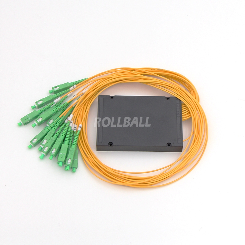
A fiber optic splitter is a device that splits the fiber optic light into several parts by a certain ratio. For example, when a beam of fiber optic light transmitted from a 1X4 equal ratio splitter, it will be divided into 4-fiber optic light by equal ratio that is each beam is 1/4 or 25% of the original source one. A Optical Splitter is different from WDM. WDM can divide the different wavelength fiber optic light into different channels. fiber optic splitter divide the light power and send it to different channels.
Most Splitters available in 900um loose tube and 250um bare fiber. 1*2 and 2*2 couplers come standard with a protective metal sleeve to cover the split. Higher output counts are built with a box to protect the splitting components.
Testing a coupler or splitter (both names are used for the same device) or other passive fiber optic devices like switches is little different from testing a patch cord or cable plant using the two industry standard tests, OFSTP-14 for double-ended loss (connectors on both ends) or FOTP-171 for single-ended testing.
Important Note! Mode Conditioning can be very important to testing couplers. Some of the ways they are manufactured make them very sensitive to mode conditioning, especially multimode but even singlemode couplers. Singlemode couplers should always be tested with a small loop in the launch cable (tied down so it does not change and set the 0dB reference with the loop.) Multimode couplers should be mode conditioned by a mandrel wrap or similar to ensure consistency.
Let’s start with the simplest type. Shown below is a simple 1X2 splitter with one input and two outputs. Basically, in one direction it splits the signal into 2 parts to couple to two fibers. If the split is equal, each fiber will carry a signal that is 3dB less than the input (3dB being a factor of two) plus some excess loss in the coupler and perhaps the connectors on the splitter module. Going the other direction, signals in either fiber will be combined into the one fiber on the other side. The loss is this direction is a function of how the coupler is made. Some couplers are made by twisting two fibers together and fusing them in high heat, so the coupler is really a 2X2 coupler in which case the loss is the same (3dB plus excess loss) in either direction. Some splitters use optical integrated components, so they can be true splitters and the loss in each direction may different.
So for this simple 1X2 splitter, how do we test it? Simply follow the same directions for a double-ended loss test. Attach a launch reference cable to the test source of the proper wavelength (some splitters are wavelength dependent), calibrate the output of the launch cable with the meter to set the 0dB reference, attach to the source launch to the splitter, attach a receive launch cable to the output and the meter and measure loss. What you are measuring is the loss of the splitter due to the split ratio, excess loss from the manufacturing process used to make the splitter and the input and output connectors. So the loss you measure is the loss you can expect when you plug the splitter into a cable plant.
To test the loss to the second port, simply move the receive cable to the other port and read the loss from the meter. This same method works with typical PON splitters that are 1 input and 32 outputs. Set the source up on the input and use the meter and reference cable to test each output port in turn.
What about the other direction from all the output ports? (In PON terms, we call that upstream and the other way from the 1 to 32 ports direction downstream.) Simply opposite the direction of the test. If you are tesing a 1X2 splitter, there is just one other port to test, but with a 1X32, you have to move the source 32 times and record the results on the meter.
What about multiple input and outputs, for example a 2X2 coupler? You would need to test from one input port to the two outputs, then from the other input port to each of the two outputs. This involves a lot of data sometimes but it needs to be tested.
There are other tests that can be performed, including wavelength variations (test at several wavelengths), variations among outputs (compare outputs) and even crosstalk (put a signal on one output and look for signal on other outputs.)
Once installed, the splitter simply becomes one source of loss in the cable plant and is tested as part of that cable plant loss for insertion loss testing. Testing splitters with an OTDR is not the same in each direction.